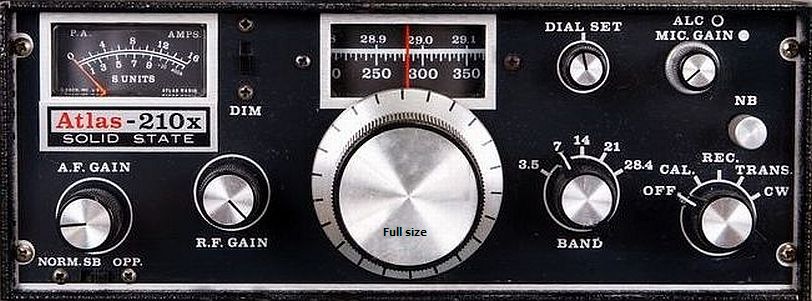
Atlas-210x 17m Modification
My Atlas transceivers are fitted with PC-100 PCB's.
INTRODUCTION
It was examined if it was feasible sacrificing 10 m for 17 m because I rarely use 10 m. When one take a closer look of the VFO range for 40 m, it appears that it is suitable for 17 m: 12520-13020 (VFO 40 m) + 5.250 (IF) = 17770-18270 MHz.
CONVERSION 28 MHz » 18 MHz
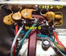
A test showed that the conversion was not difficult. Disconnect the 28 MHz wire of VFO's wafer A to L403 and rewire to 7 MHz contact lug of wafer A. In my set 2 × 4.7 pF (C414) are connected in series at waver B on 28 MHz. Shortcut one so that only 4.7 pF is in parallel to C415. With this modification trimmer C415 can adjust for 18.000 MHz corresponding to zero at the beginning of the scale.
With the band switch on 28.4 the VFO range becomes 12750-13250 MHz. The transceiver is ready for 18000-18500 MHz, scale from 0 to 500.
The 17 m band could be heard using 10 m receiver input circuit (PC800). During an output test with dummy load a 18 MHz signal was detected. Both were hopeful reasons to continue the project.
|
|
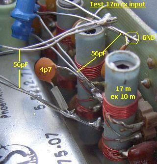
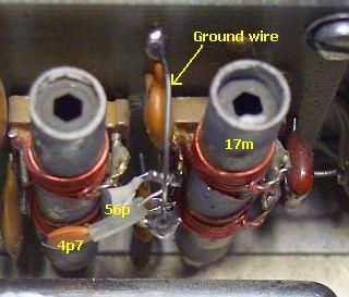
Install 56 pF in parallel to C814, C815 or replace about 100 pF in parallel to each coil.
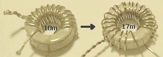
Replace 16 by 24 turns, tap at 4 turns. |
Modified receiver input circuit.
Final installation. |
RECEIVER INPUT TUNING PC-800: After a temporary 56 pf installation parallel to C814, C815 and trimming slugs, S-meter reading (S9 = 50µV) was equal to the other frequency bands. To keep it simple I did not disassemble PCB but used the present solder points for final installation. One leg of C815 was used as a grounding point. Both ferrite slugs were adjusted for maximum S meter reading on 18.110 MHz.
TRANSMITTER INPUT TUNING PC-900: The transmitter input tuning (PC900) were examined. The 15 m and 20 m toroids had each 24 turns, 10 m toroid only 16 turns. Therefore, both toroids of the 10 m band were rewound with 24 turns, tap at 4 turns. After installation and adjusting 18.110 MHz circuits, 100 W output power could be obtained through 10 m (PC1010) low pass filter (LPF) of the power amplifier.
|
|
Low pass filter achter de PA
|
|
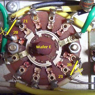
Het low pass filter voor 15 m wordt voor 17 m gebruikt, 10 m is ontkoppeld |
|
The (LPF) is hidden in the Alu box with the heatsink. If that is removed you have access to wafer E of the band switch. For the 17 m band one may modify 10 m LPF, but that is a chore. We simply use 15 m LPF for 17 m. At wafer E (fig») disconnect wires to 10 m LPF and rewire to 15 m LPF. Finally solder wire ends across 10 m and 15 m contact lugs.
See my other Atlas-210x/215x articles:
General information AGC modification Speech processor VFO stabilizer Post mixer amplifier![]()